
System Information
Chapter 7.2: Viewing System Information
A detailed, read-only manifest of your node's hardware components and their specifications.
ℹ️ System Information Access
Available to: All user roles
Scope: Individual node level
Permissions: Read-only for all users
Data Source: Retrieved directly from node's BMC via Redfish protocol
Overview: Your Digital Asset Tag
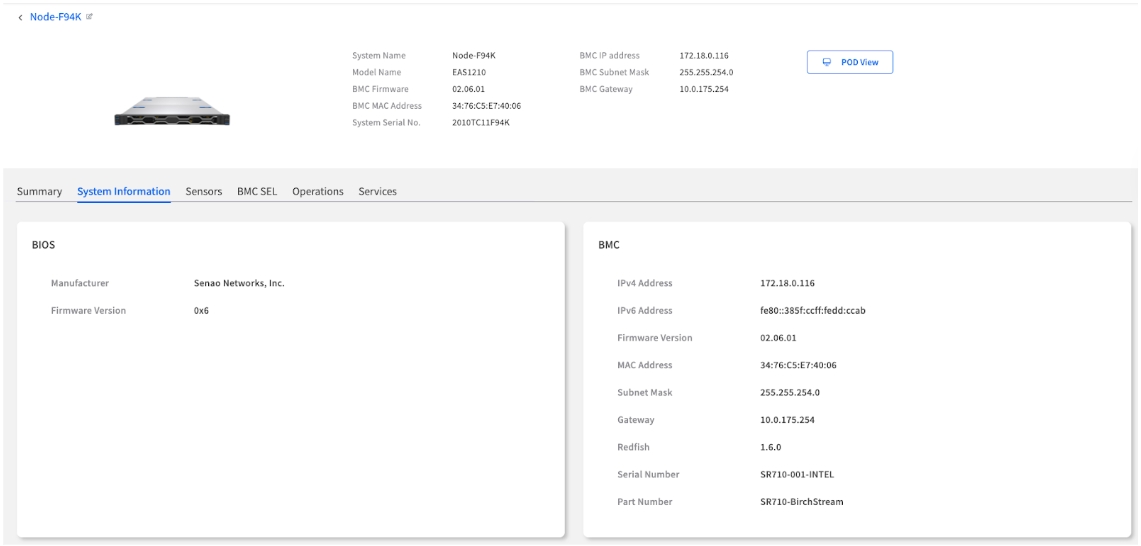
The System Information tab is your node's digital asset tag. It provides a complete and detailed inventory of every physical hardware component installed in the machine, from the exact model of the CPU to the part number of each individual memory module.
This information is fetched directly from the node's BMC, ensuring it's an accurate reflection of the physical hardware. This page is read-only and serves three primary real-world purposes:
Asset Management: Quickly audit hardware without needing physical access.
Technical Support: Provide precise component details to support teams.
Upgrade & Compatibility Planning: Verify current specs before ordering new parts.
Hardware Component Deep Dive
The page organizes the hardware into logical, collapsible categories. Click on any category header (e.g., BIOS, BMC, CHASSIS) to expand it and view detailed specifications.
🖼️ **
Navigation Tips
Expandable Sections: Click category headers to expand/collapse detailed views.
Complete Inventory: All sections provide comprehensive component-level details.
Copy-Friendly Format: Information is formatted for easy copying to support tickets.
Core Firmware & Identity
These sections provide version and identity information for the node's core firmware and management controller.
BIOS
Manufacturer
The vendor of the BIOS firmware (e.g., Senao Networks, Inc.).
Identifying the source of firmware updates.
Firmware Version
The version of the system's BIOS/UEFI (e.g., 0x6). Critical for checking compatibility with new OS versions or hardware.
OS compatibility verification, security updates, feature availability.
BMC (Baseboard Management Controller)
IPv4 Address
The primary management IP address assigned to the BMC.
Network connectivity, accessing BMC web UI.
IPv6 Address
The IPv6 management address assigned to the BMC, if configured.
Network connectivity in IPv6 environments.
Firmware Version
The version of the BMC's firmware (e.g., 02.06.01). Essential for security audits and ensuring you have the latest management features.
Security compliance, management feature availability, Redfish compatibility.
MAC Address
The unique hardware address of the BMC's network interface (e.g., 34:76:C5:E7:40:06). Needed for network troubleshooting and configuring DHCP reservations.
Network configuration, DHCP reservations, MAC-based security.
Subnet Mask
The subnet mask associated with the BMC's IPv4 address.
Verifying network configuration.
Gateway
The default gateway IP address used by the BMC.
Verifying network configuration for remote access.
Redfish
The version of the Redfish schema supported by the BMC (e.g., 1.6.0). Indicates API capabilities.
Automation scripting, integration with other management tools.
Serial Number
The serial number associated with the BMC module itself (may differ from Chassis SN).
BMC-specific support or replacement.
Part Number
The manufacturer's part number for the BMC module.
BMC-specific support or replacement.
Physical Chassis & Mainboard
These sections detail the physical enclosure and main circuit board of the node, providing the primary identifiers for the machine as a whole.
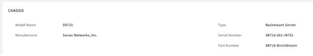
CHASSIS
Model Name
The model name of the node's chassis (e.g., SR710).
Hardware compatibility and specification verification.
Manufacturer
The manufacturer of the chassis (e.g., Senao Networks, Inc.).
Identifying the hardware vendor.
Type
The physical form factor of the chassis (e.g., Rackmount Server).
Data center planning, rack compatibility.
Serial Number
The unique serial number of the chassis. This is often the primary serial number you need for asset tagging and support contracts.
Primary Asset ID - Use for support tickets and inventory.
Part Number
The manufacturer's part number for the chassis assembly.
Ordering replacement chassis parts.
Asset Management Tip: The Chassis Serial Number should be your primary identifier in all asset management systems, support tickets, and inventory records.
BASEBOARD
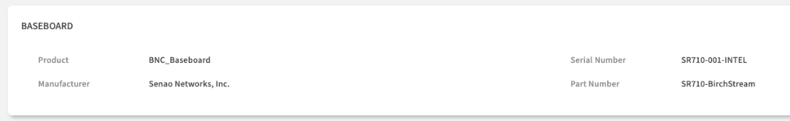
Product
The product name of the motherboard (e.g., BNC_Baseboard).
Identifying the motherboard model.
Manufacturer
The manufacturer of the motherboard (e.g., Senao Networks, Inc.).
Identifying the hardware vendor.
Serial Number
The unique serial number of the motherboard.
Motherboard-specific support or warranty claims.
Part Number
The manufacturer's part number for the motherboard. Useful for identifying specific board revisions.
Motherboard compatibility and replacement part ordering.
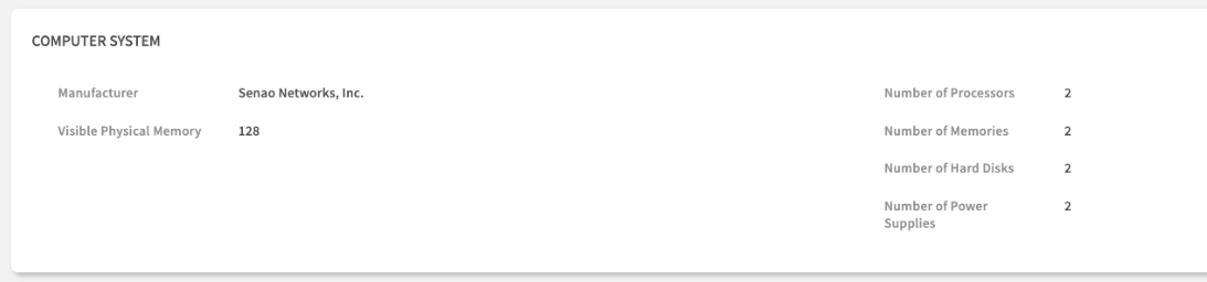
Compute & Memory Resources
Here you can find a detailed breakdown of the node's core computing and memory resources.
COMPUTER SYSTEM
Manufacturer
The manufacturer of the overall system (e.g., Senao Networks, Inc.).
Identifying the system integrator/vendor.
Visible Physical Memory
The total amount of installed RAM detected by the system (e.g., 128 GB). A key specification for performance and capacity planning.
Performance tuning, capacity planning, OS requirements check.
Number of Processors
The count of physical CPU sockets populated on the motherboard (e.g., 2).
Verifying CPU configuration, licensing calculations.
Number of Memories
The count of installed physical memory modules (DIMMs).
Verifying memory configuration, troubleshooting.
Number of Hard Disks
The count of detected storage drives (HDDs/SSDs).
Verifying storage configuration.
Number of Power Supplies
The count of installed Power Supply Units (PSUs).
Verifying power redundancy configuration.
PROCESSOR
This lists each physical Central Processing Unit (CPU) installed in the node.
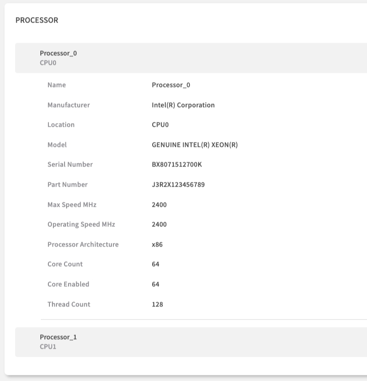
Name
An identifier for the CPU socket (e.g., Processor_0).
Locating the specific CPU.
Manufacturer
The vendor of the CPU (e.g., Intel(R) Corporation).
Identifying the CPU manufacturer.
Location
The physical socket identifier on the motherboard (e.g., CPU0).
Physical identification for replacement/upgrade.
Model
The specific model name of the CPU (e.g., GENUINE INTEL(R) XEON(R)). Determines its performance capabilities.
Performance planning, software licensing, compatibility checks.
Serial Number
The serial number of the specific CPU chip (if available).
CPU-specific tracking or warranty.
Part Number
The manufacturer's part number for the CPU.
Ordering exact replacement CPUs.
Max Speed MHz
The maximum rated clock speed of the CPU.
Performance benchmarking.
Operating Speed MHz
The current or base operating speed of the CPU.
Performance verification.
Processor Architecture
The instruction set architecture (e.g., x86).
OS and software compatibility.
Core Count
The number of physical cores on the CPU chip (e.g., 64). Key metric for performance and licensing.
Workload capacity planning, per-core licensing.
Core Enabled
The number of cores currently enabled.
Verifying CPU configuration.
Thread Count
The number of logical threads the CPU supports (e.g., 128, often 2x Core Count with hyper-threading). Key metric for parallel processing performance.
Workload capacity planning, performance tuning.
PHYSICAL MEMORY
This section lists each individual memory module (DIMM) installed in the node, which is invaluable for troubleshooting and planning upgrades.
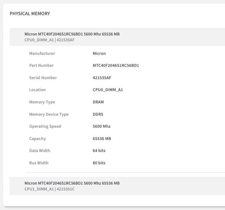
Header
(e.g., Micron...)
A summary line often including Manufacturer, Part Number, Speed, Size, Location, and Serial Number.
Quick identification.
Manufacturer
The vendor of the DIMM (e.g., Micron).
Verifying memory vendor.
Part Number
The specific part number of the memory module. Use this to ensure you order an identical, compatible replacement or upgrade.
Procurement - Compatible part ordering.
Serial Number
The unique serial number of the individual DIMM.
Warranty claims, tracking specific modules.
Location
The physical slot on the motherboard where the DIMM is installed (e.g., CPU0_DIMM_A1). Crucial for telling a technician exactly which DIMM to replace.
Field Service - Exact replacement location.
Memory Type
The general type of memory (e.g., DRAM).
Basic classification.
Memory Device Type
The specific memory technology standard (e.g., DDR5).
Compatibility checks.
Operating Speed
The speed at which the memory is currently operating (e.g., 5600 Mhz). May differ from max speed due to system configuration.
Performance verification, compatibility checks.
Capacity
The storage capacity of the individual DIMM (e.g., 65536 MB = 64 GB).
Capacity Planning - Memory configuration analysis.
Data Width
The width of the data bus for the module (e.g., 64 bits). Standard for most DIMMs.
Technical specification.
Bus Width
The total bus width including ECC bits (e.g., 80 bits for ECC DDR5). Indicates ECC capability.
Verifying ECC support.
Power & Storage
This section details the power supply and storage components installed in the node.
POWER SUPPLY
This lists each installed Power Supply Unit (PSU).
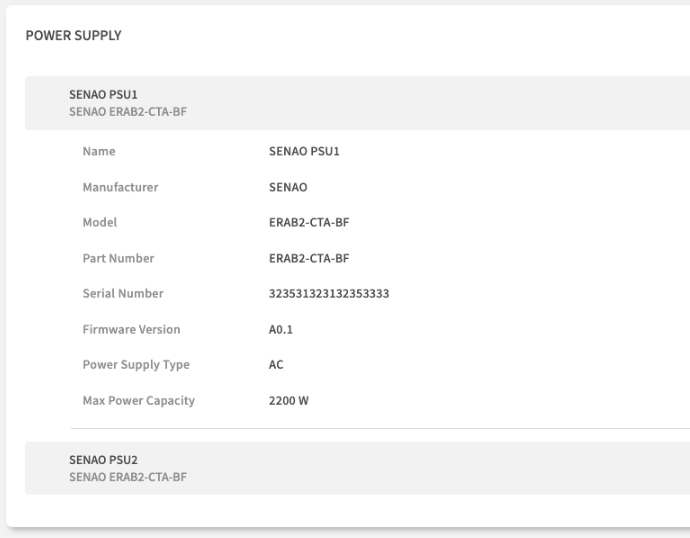
Header
(e.g., SENAO PSU1...)
A summary line often including Name, Model.
Quick identification.
Name
The identifier for the PSU slot (e.g., SENAO PSU1).
Locating the specific PSU.
Manufacturer
The vendor of the PSU (e.g., SENAO).
Identifying the PSU vendor.
Model
The specific model number of the PSU.
Replacement part ordering.
Part Number
The manufacturer's part number for the PSU.
Replacement part ordering.
Serial Number
The unique serial number of the PSU. Often required when requesting a warranty replacement for a failed unit.
Warranty Claims - PSU replacement.
Firmware Version
The firmware version running on the PSU's internal controller (if applicable).
PSU feature updates or bug fixes.
Power Supply Type
The type of input power (e.g., AC).
Data center power compatibility.
Max Power Capacity
The maximum power output of the PSU in watts (e.g., 2200 W). Important for data center power planning.
Power Planning - Data center capacity, redundancy calculations.
STORAGE
This lists each installed storage drive (HDD/SSD).
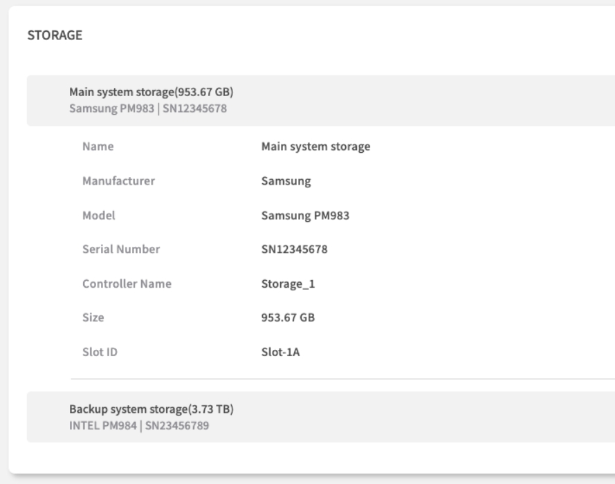
Header
(e.g., Main system storage...)
A summary line often including Name, Size, Model, Serial Number.
Quick identification.
Name
A descriptive name for the storage device or volume (e.g., Main system storage).
Identifying the drive's purpose.
Manufacturer
The vendor of the drive (e.g., Samsung, INTEL).
Looking up drive specifications or firmware.
Model
The specific model number of the drive (e.g., Samsung PM983, INTEL PM984). Useful for looking up performance specs or firmware updates for the drive itself.
Performance Planning - Drive specifications, compatibility.
Serial Number
The unique serial number of the drive (e.g., SN12345678). Needed for warranty claims.
Warranty Claims - Drive replacement.
Controller Name
The name of the storage controller managing this drive (e.g., Storage_1).
Identifying the connection path.
Size
The storage capacity of the drive (e.g., 953.67 GB, 3.73 TB).
Capacity Planning - Storage allocation.
Slot ID
The physical slot or bay identifier where the drive is installed (e.g., Slot-1A).
Physical location for replacement.
Practical Usage Scenarios
Support Ticket Creation
Information Gathering Workflow:
System Identity: Copy Chassis Serial Number.
Firmware Versions: Note BIOS Firmware Version and BMC Firmware Version.
Component Details: If the issue relates to a specific part (e.g., memory), include its Part Number, Serial Number, and Location (from Physical Memory section).
Configuration Context: Provide memory, storage, and CPU configuration summaries (e.g., total RAM from Computer System, CPU Model/Count, Storage drive models/sizes).
Hardware Upgrade Planning
Pre-Purchase Verification:
Memory Expansion: Check existing DIMM Part Numbers, Memory Device Type (e.g., DDR5), and Operating Speed to ensure compatibility. Note the physical Location to identify empty slots.
Storage Upgrades: Verify drive Models and interface (Controller Name) compatibility. Check physical Slot ID availability.
Power Requirements: Confirm total Max Power Capacity from all PSUs is sufficient for new components.
Compatibility Matrix: Cross-reference all intended components (CPU, Memory, Storage) against vendor compatibility documentation using the exact Model and Part Numbers found here.
Asset Inventory Management
Regular Audit Process:
Primary Identification: Use Chassis Serial Number as the key identifier in your asset database.
Component Tracking: Record Part Numbers and Serial Numbers for key components like Motherboard (Baseboard), CPUs, Memory DIMMs, PSUs, and Storage drives.
Configuration Documentation: Document current hardware configuration (CPU Model/Count, Total Memory, Storage Capacity/Models).
Change Management: When hardware is replaced or upgraded, update your asset records using the information from this tab to reflect the new state.
Chapter Summary & Key Takeaways
Your Go-To for Support: When you open a support ticket, this page has all the serial numbers, part numbers, and firmware versions you'll need.
Upgrade with Confidence: Before buying new RAM or drives, check the Part Numbers, Type, and Speed here to ensure you're ordering a compatible component.
Remote Asset Tagging: Use the Chassis Serial Number as the primary identifier for all your asset management records, eliminating the need for physical checks.
Real-Time Accuracy: All data is fetched directly from the BMC, ensuring accurate hardware inventory.
Complete Component View: From BIOS versions to individual DIMM locations, this tab provides comprehensive hardware documentation covering nearly every field shown in the UI.
What's Next:
Chapter 7.3 will explore the Sensors tab, where you'll learn to monitor real-time hardware health and environmental conditions in detail.
💡 Pro Tip: Bookmark key information like Chassis Serial Numbers and frequently needed Part Numbers for quick reference during support calls and maintenance planning.