
POD View
Chapter 8: Visualizing Topology with POD View
A powerful drag-and-drop tool for designing, planning, and documenting your logical rack layouts.
ℹ️ POD Topology
Available to: All user roles
Scope: POD level (for editing) / Organization & HV levels (view-only)
Permissions:
Admin roles: Full topology management (add, edit, delete) at the POD level.
Viewer roles: View-only visualization.
Note: You can only create or modify rack layouts when you are in the POD scope. Org/HV scopes provide a read-only aggregated view.
Overview: Your Digital Whiteboard for Rack Planning
The MANAGE → POD View is your digital whiteboard for creating a logical representation of your data center racks. It's a powerful planning and documentation tool that allows you to design, visualize, and share your rack layouts without ever stepping foot in the data center. Its core purpose is to bridge the gap between your physical hardware and your logical management structure.
mportant: This is a Planning Tool, Not a Live Monitor
It is crucial to understand that POD View is for organizational and planning purposes only. The arrangements you make here (e.g., placing a node in a rack) do not affect the node's actual operation, network configuration, or management status.
Why Use POD View? Your Primary Use Cases
Before diving into the "how," it's important to understand the "why." POD View is a strategic tool designed to solve several key challenges in data center management.
Initial Data Center Design
Before any hardware is installed, use POD View and Virtual Devices to create a complete logical map of your planned environment
Plan layouts including servers, switches, and PDUs
Capacity Planning
As your infrastructure grows, use Virtual Devices to plan for future expansion and reserve rack space
Visualize future growth and space allocation
Physical Maintenance & Identification
Help technicians quickly and accurately identify the logical location of a specific node within a rack
Reduce human error during physical work
Documentation and Reporting
Click the Export button to generate a PDF of your layout for official technical documentation
Create standardized rack documentation
Understanding the POD View Workspace
The interface is divided into three main areas. The canvas is where you build, the device panel is your inventory of building blocks, and the action buttons are your tools.
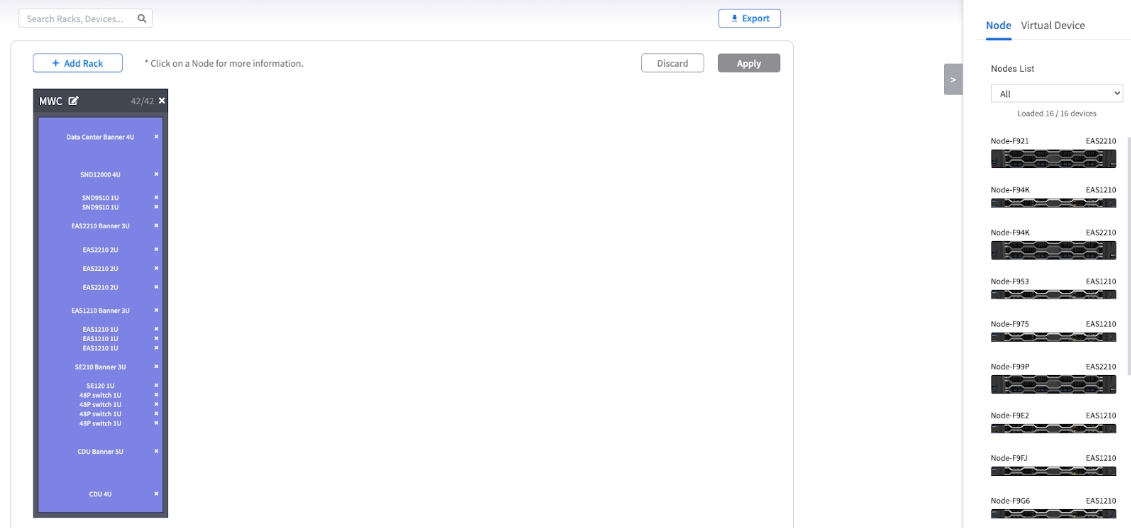
The Rack Canvas
This is your digital data center floor, where you place and organize your virtual racks to mirror your physical layout.
The Device Panel
This sidebar is your palette of all available equipment, separated into the hardware you actually manage and the conceptual items you need for planning.
Node Tab
Lists all the real, managed EnGenius nodes in this POD
Place actual managed hardware
Virtual Device Tab
Contains non-real, placeholder devices you can create for planning
Plan for switches, firewalls, or future servers
The Action Buttons
This is your command toolbar for managing the entire layout.
Add Rack
Opens the dialog to create new racks on your canvas
Create rack containers
Apply / Discard
Saves or cancels the changes you've made to your layout
Manage layout changes
Export
Allows you to export the current rack layout as a PDF document
Generate documentation
Building Your Topology: A Step-by-Step Guide
Follow these steps to create a visual representation of your POD's infrastructure, moving from creating the large containers (racks) to placing the individual components within them.
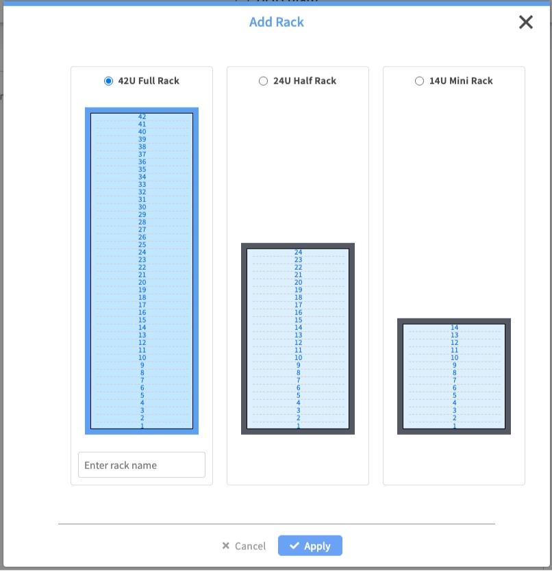
Step 1: Adding and Naming Racks
Your first step is to create the virtual racks that will serve as the containers for all your devices.
Process:
Click the + Add Rack button
In the Add Rack dialog, choose a standard size:
42U Full Rack
24U Half Rack
14U Mini Rack
Enter a descriptive Name for the rack
Click Apply
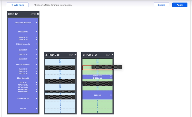
Step 2: Adding Real Nodes to Racks
Now you can place your real, managed EnGenius nodes into the racks.
Process:
In the Device Panel, select the Node tab
Use the dropdown menu to filter the list by Groups
Click and drag a node from the list and drop it into an empty slot in a rack
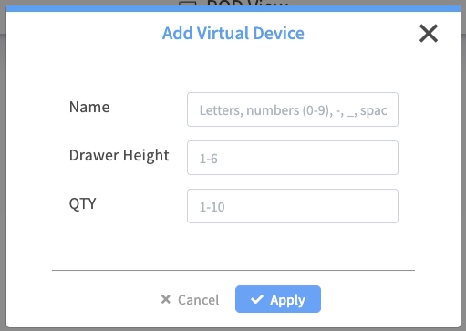
Step 3: Planning with Virtual Devices
Overview: Use virtual devices to create a complete representation of your rack space, including non-managed hardware or future additions.
Process:
Select the Virtual Device tab
Click + Add Device to create a new placeholder
Configure the placeholder's:
Name
Height (in U)
Quantity
Click Apply
Managing Your Racks and Devices
Creating the layout is just the first step. Here is how you manage, modify, and see details for the items on your canvas.
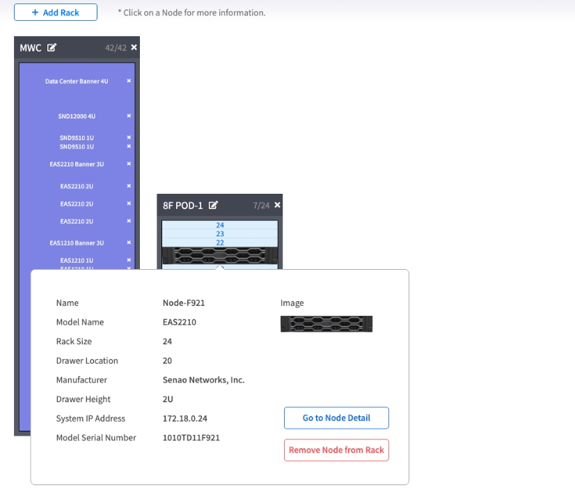
Viewing Node Details in the Rack
To quickly see the details of a node you have placed in a rack:
Hover your mouse over the node in the rack.
A tooltip will appear showing key details, such as its full Name, Model, Serial Number, and IP Address.
Editing a Rack's Name
If your naming conventions change or you made a typo:
Double-click on the rack's nameplate (the title bar of the rack).
The name will become an editable text field.
Type the new name and press Enter to confirm.
Removing a Device from a Rack
If a node is moved or decommissioned, you can remove it from the visual layout.
To Remove a Real Node:
Find the node in the rack.
Click the "X" icon on the right side of the node's entry in the rack.
The node will be removed from the rack and will reappear in the Node Tab list on the right, ready to be placed again.
To Remove a Virtual Device:
Find the virtual device in the rack.
Click the "X" icon on its entry.
The device will be removed from the rack and will reappear in the Virtual Device Tab list.
Deleting a Rack
If a rack is no longer needed:
Ensure the rack is empty. You cannot delete a rack that still contains nodes or virtual devices. Remove all items first (see step above).
Click the trash can icon (Delete) located on the rack's nameplate.
Confirm the deletion. The empty rack will be removed from the canvas.
Saving and Exporting Your Work
All your layout changes are temporary until you explicitly save them.
Control Options:
Apply: Click to save your current layout
Discard: Click to cancel all changes
Export: Click to download the current layout as a PDF file
Common Mistake: Forgetting to Click Apply
Your layout changes are not saved automatically. Always click Apply to save your work.
Chapter Summary & Key Takeaways
It's a Blueprint, Not the Building: POD View is for planning and documentation. Changes here are logical and do not affect the real nodes
Virtual Devices are for Complete Planning: Use virtual devices to represent everything in your rack—not just EnGenius nodes—for a truly accurate layout
Groups Save Time: Organize your nodes into groups in the Node List first to make finding and placing them here much easier
Apply to Save: Your work is not saved until you click the Apply button
Admin Rights for Changes: Layout modifications require Admin permissions - Viewers can visualize but cannot modify
What's Next: Now that you understand the core MANAGE module, Part 3 will explore the CONFIGURE module for POD-level automation and deployment tasks.
💡 Pro Tip: Use groups strategically in the Node List before coming to POD View - it makes finding and organizing nodes in your rack layouts much more efficient.