

Basic Troubleshooting
This chapter provides guidance for diagnosing and resolving common server problems. When an issue occurs, approaching it methodically can help you find the root cause quickly.
Best Practice: Check the BMC Event Log First
Your first step should always be to log in to the BMC web interface and check the System Event Log (SEL). The BMC logs all hardware events and will often tell you exactly what is wrong.
Common problems and solutions
System won't power on
If the server shows no signs of life, follow these steps:
Check the source: Ensure the rack's PDU is switched on and functioning.
Check the cables: Confirm both power cords are firmly plugged into the server's PSUs and the PDUs.
Check the PSU LEDs: Look at the small LED indicators on the power supply units themselves. A green light indicates the PSU is receiving power. If there is no light or an amber light, the PSU may be faulty or not receiving power.
No video output / No POST
"No POST" means the server is not completing its Power-On Self-Test.
Check the remote console first: Always use the BMC's remote KVM to check for video output. This tells you if the problem is with the server itself or just the local monitor connection.
Listen for beep codes: If the system speaker is connected, the server may emit a pattern of beeps that indicate the specific problem (e.g., a memory or CPU issue).
Reseat key components: Power off and disconnect the server. Open the chassis and carefully reseat the memory modules and any expansion cards. An improperly seated component is a very common cause of POST failures.
Memory errors
If the system boots but reports memory errors, or fails to boot with a memory error code:
Check the population rules: Ensure the DIMMs are installed in the correct slots according to the guidelines in Chapter 5.
Isolate the faulty module: If you have multiple DIMMs, try booting with a minimal configuration (one DIMM per CPU). Add modules back one by one until the error reappears to identify the faulty DIMM.
Check the system event log (SEL): The BMC logs all hardware errors, including which specific DIMM slot is reporting a problem.
Fans spin at full speed
If the system fans run at 100% speed continuously and do not slow down after boot:
Check for thermal events: Use the BMC interface to check for any high-temperature warnings. Ensure the ambient room temperature is within the specified limits.
Verify airflow: Make sure the chassis top cover is correctly installed and secured. Check that no cables are blocking the fans or airflow paths inside the chassis.
Check for failed sensors: A failed temperature sensor can cause the BMC to ramp up the fans as a precaution. Check the BMC event log for any sensor-related errors.
BMC/IPMI is not responding
If you cannot reach the BMC's web interface or get a response from ping:
Check the physical connection: Ensure the network cable is securely plugged into the dedicated MGMT port and the network switch. Check the link lights on the port.
Check for IP conflicts: Make sure no other device on the network is using the same IP address as the BMC.
Perform a cold reboot: As a last resort, shut down the server and disconnect the power cords for 30 seconds. This will force the BMC to completely restart.
Drive not detected in OS
If a drive is not visible in the operating system or during installation:
Check the physical seating: Ensure the drive carrier is fully inserted and locked into the drive bay.
Check the drive LED: A green LED on the carrier indicates the drive has power. If there is no light, the drive may not be seated correctly.
Check the BIOS: Reboot the server and enter the BIOS setup. Check the storage or NVMe configuration pages to see if the drive is detected at the hardware level.
Check the drivers: For RAID/VROC configurations, ensure the correct storage controller driver is loaded during the OS installation.
Interpreting status LEDs
The LEDs on the server provide a quick visual diagnosis of its status. This section details the function of each major LED.
Front Panel LEDs
LED
COLOR/STATE
DESCRIPTION
Power LED
Green (Solid)
System is powered on (ACPI S0).
Blinking
System is in sleep mode.
Off
System is off (ACPI S4/S5).
UID LED
Blue
System identified via command or button.
System Status LED
Green
BMC is initializing.
Red
BMC anomaly or system failure detected.
Off
System is running normally.
Alarm LED
Red
System failure.
Green
BMC initializing.
Off
Normal operation.
M.2 Activity LED
Amber
M.2 drive is present, no activity.
Blinking
M.2 drive is being accessed.
NIC Link LED
Green / Orange
Link established (speed dependent).
NIC Activity LED
Blinking
Network traffic is detected.
Drive Bay LEDs
LED Name
Color
Description
Activity
Green
Blinking: Read/write in progress.
Status
Amber/Red
Drive fault or predictive failure.
Power
Solid Green
Drive is powered on.
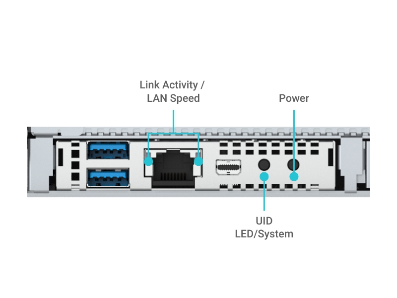
Network Port (RJ-45) LEDs
Each RJ-45 LAN port includes integrated LEDs to show link and activity status
LED Name
Color
Description
Link/Speed
Green
1 Gbps connection established.
Amber
100 Mbps connection.
Off
No link detected.
Activity
Blinking
Network traffic detected.
IPMI/BMC LED
Some systems include a dedicated LED for the BMC, which may be visible on the front panel or internally on the motherboard.
LED Behavior
Description
Blinking (1Hz)
BMC running normally.
Fast blinking
BMC initializing or updating.
Off
BMC not powered.
Understanding BIOS POST codes
If the server hangs during boot, the last POST code displayed can tell you at what stage the failure occurred.
POST Code
Stage
Description / Common Causes
19
Memory Initialization
Detecting and initializing DRAM. Check DIMM seating, population rules.
4F
DXE Phase
DXE IPL started (BIOS driver loading). Normal if system proceeds past it.
6F
DXE Initialization
BMC, USB, PCIe devices being initialized. May hang if faulty PCIe card installed.
A2
IDE/SATA Detection
Detecting storage controllers/devices. Check cable, drive type, BIOS mode.
B2
Option ROM Init
Initializing VGA/RAID/NIC ROMs. Remove/replace problematic add-in cards.
D7
Input Device Init
Keyboard or input not detected. OK for headless systems.
FF
Fatal Error / Halt
System failed to complete POST. Reset CMOS, isolate components, check PSU.
Last updated