

Installing a CPU and Heatsink
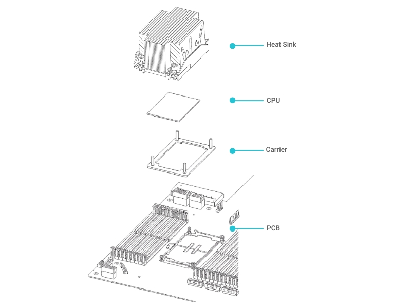
This chapter provides detailed instructions for installing or replacing a CPU. In modern servers, the processor (CPU) and its heatsink are installed as a single unit, called a Processor Heatsink Module (PHM). This process requires precision and careful handling.
Warning: Handle with Extreme Care
The CPU and its socket are extremely sensitive. A single bent pin or a particle of dust can cause a system failure. Always perform this work in a clean, well-lit area, and follow all ESD safety guidelines.
Preparing the processor heatsink module (PHM)
Your first task is to assemble the PHM by securing the new CPU into its carrier and then attaching the carrier to the heatsink.
To assemble the PHM:
Attach the processor to the carrier.
Hold the processor by its edges, with the gold contacts facing up.
Align the small triangle on the processor (Pin 1 indicator) with the triangle on the carrier frame.
Gently lower the processor into the carrier until it sits flat.
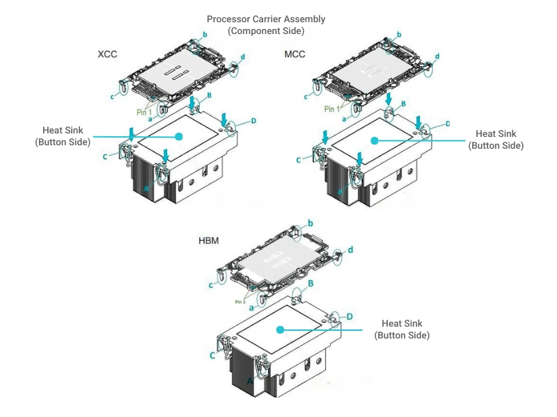
Attach the carrier assembly to the heatsink.
Turn the heatsink upside down.
Align the processor carrier assembly with the heatsink, matching the triangle indicators.
Press the assembly down firmly until it snaps into the four retention clips on the heatsink.
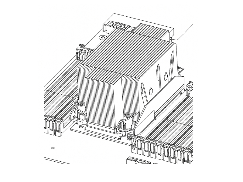
Installing the PHM on the motherboard
Once the PHM is assembled, you can install it onto the motherboard.
To install the PHM:
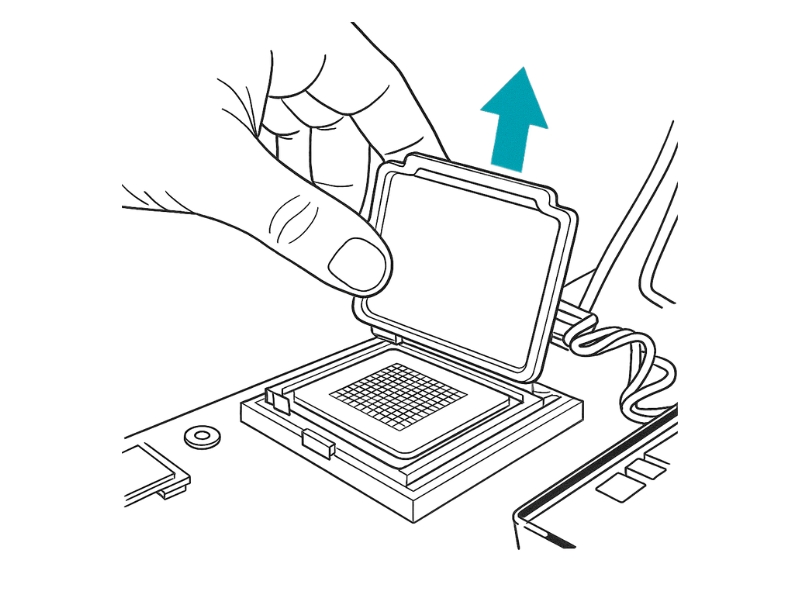
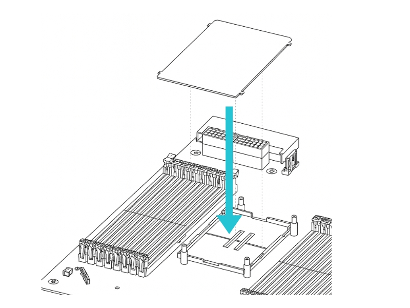
Remove the protective socket cover. If there is a plastic cover on the CPU socket, remove it by gently squeezing the tabs and lifting it off. Keep this cover in a safe place; you'll need it if you ever remove the CPU and need to protect the socket.
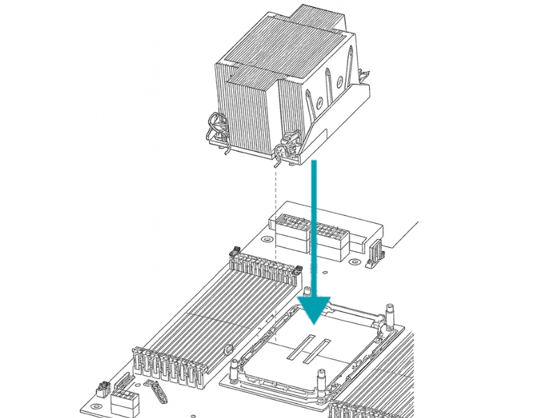
Align the PHM with the socket. Carefully hold the PHM over the socket. Align the guide markings on the PHM with the alignment posts on the motherboard socket.
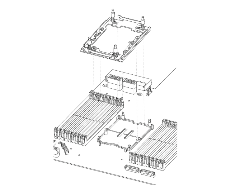
Lower the PHM and secure it. Gently lower the PHM straight down onto the socket. Do not slide or tilt it.
Tighten the heatsink screws in sequence. Using a T30 torque driver, tighten the four captive screws in the exact sequence shown below (1 → 2 → 3 → 4).
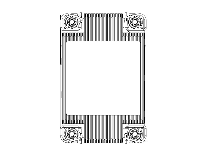
Purpose: Why is the sequence so important? Tightening the screws in a cross pattern ensures that pressure is applied evenly across the processor. This prevents the CPU from tilting in the socket and guarantees optimal contact between the processor and the heatsink for effective cooling.
Torque Specifications and Handling
Use the correct tools and follow the torque specifications precisely to avoid damaging the components.
Component
Torque Spec
(Nm / in-lbf)
Tool Type
Installation Sequence
Notes
CPU Carrier Screws
0.5 Nm (4.4 in-lbf)
T20 Torx Driver
Diagonal cross pattern (1–4)
Hand-tighten evenly; avoid over-torque.
Heatsink Screws
1.2 Nm (10.6 in-lbf)
Torque-limiting driver
X-pattern (1–2–3–4)
Wait 30 sec between each torque pass.
Retention Frame
0.8 Nm (7.1 in-lbf)
5 mm Hex Socket
Clockwise from upper-left corner
Ensure carrier sits flat before torque.
VRM Heatsink
0.6 Nm (5.3 in-lbf)
Phillips #1
Sequential
Do not skip screws.
Do’s
Don’t
Hold the processor by its edges.
Do not touch the pins, gold fingers, or underside contacts.
Always wear an ESD strap and work on an anti-static mat.
Do not place the CPU on metal, paper, or rough surfaces.
Inspect for bent pins or contaminants before installation.
Do not force the CPU into the socket if resistance is felt.
Align triangle or notches properly before seating.
Do not rotate or wiggle the CPU once aligned in the socket.
Use a processor tray or ESD-safe clamshell during transport.
Do not carry the CPU loosely in hand or pocket.
Verify CPU model compatibility with socket and carrier.
Do not install unsupported CPU SKUs in incorrect carriers.
Removing a PHM
To remove a PHM for a CPU upgrade or replacement, you'll follow the installation steps in reverse.
Using a T30 torque driver, loosen the four screws in the reverse sequence: 4 → 3 → 2 → 1.
Once the screws are fully loosened, gently lift the PHM straight up and away from the socket.
If you are not immediately installing a new PHM, place the protective plastic cover back onto the empty CPU socket.
Last updated